Connecting the Medisana BS440 Bluetooth scale (part 5)

Triggered by a comment on episode 1 of this blog i decided to use Domoticz to visualize the measurements in a graph. I use Domoticz to control my home since july 2013 and it has proven to be very reliable.

To graph the weight first a “virtual sensor” must be created. First find a unique index and paste the url below in your browser:

http://domoticzip:8080/json.htm?type=command&param=udevice&hid=2&did=60&dunit=4&
dtype=93&dsubtype=1&nvalue=0&svalue=75.0
* did=60 represents the device ID number for this device 
  (could be any unique number). Make a note of it. 
  Upon creation the device will be given an unique index.
* dtype=93 refers to the BWR102 device, a Oregon Scientific connected scale we mimic.
* svalue=75.0 refers to the weight. Every call to this URL will update the value.

After creation of the virtual sensor, push the green button to have the sensor showing up on the “Other devices” tab:
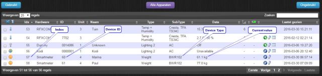
Domoticz1

Other Devices tab:

Domoticz2

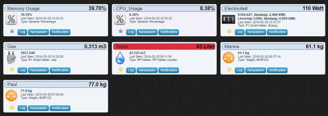
Now the sensors are ready the BS440 program can call the sensor URL with the appropriate Device number and weight (see BS440domoticz.py). In the .ini file the Domoticz connection parameters (IP-adres and username/password) can be entered.

Now every time a user steps on the scale the weight will be logged and graphed.

Domoticz3

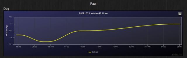
To have consistent results it is advised to do your weighings at the same time of day. In my case this will be between 07:00 and 08:00 in the morning (8:00 – 11:00 in the weekends). I use an IP controlled switch based on a Sonoff ESP8266 based 220V switch flashed with ESP Easy firmware. Now Domoticz can switch on/off the Raspberry through WiFi by calling the ip address of the Sonoff like

http://ip-address/control?cmd=gpio,12,1 (=on) 
http://ip-address/control?cmd=gpio,12,0 (=off)

Domoticz4

Before switching off at 8:15 (11:15 in the weekeinds) be sure that a cron job did a shutdown earlier to not corrupt the flash card. Also when powering up, the “python BS440.py” needs to be started automatically through BS440.sh and a @reboot cron. These are the cron definitions to accomplish this:

@reboot sh /home/pi/BS440.sh > /home/pi/cronlog 2&1
0 8 * * 1,2,3,4,5 sudo shutdown -h +0
0 11 * * 0,6 sudo shutdown -h +0 

A 1 minute sleep is inserted in BS440.sh to have a stable booted Raspberry before starting the bluetooth communications in background.


#!/bin/sh
cd /
cd home/pi
sleep 1m
sudo python BS440.py &
cd /
Posted in FF32 | Tagged , , , , , , , | 49 Comments

Connecting the Medisana BS440 Bluetooth scale (part 4)

To start with: i am not a professional programmer, never was, never will be. Started off with some assembly on a 8 bit (yes!) SC/MP processor in my early days and ended with Turbo Pascal on MS-DOS6.2 as highest level of sophistication. Maybe that’s why i enjoy poking around on the credit-card size Raspberry in Python. The wealth of internet resources surely helps. This journey learned me about C-structs, callback routines, running shell commands, logging, parsing ini files, exception handling, pep8 and of course a little bluetooth. The complete code can be found  on my Github pages

The sequence of commands we want to issue through gatttool after being connected to the scale are basically these (when issued from the shell, pygatt will use the interactive mode of gatttool):

gatttool -t random -b F1:37:57:XX:XX:XX --char-write --handle 0x001f -n 0200
gatttool -t random -b F1:37:57:XX:XX:XX --char-write --handle 0x001c -n 0200
gatttool -t random -b F1:37:57:XX:XX:XX --char-write --handle 0x0026 -n 0200
gatttool -t random -b F1:37:57:XX:XX:XX --char-write-req --handle 0x0023 -n 0000000000 --listen

But the problem is we need to connect first and connecting is only possible for about one minute after the person has stepped onto the scale and we don’t know when that will be. The first attempt was just endless keep on trying to connect with 5 second timeouts. This is what it looked like:

adapter = pygatt.backends.GATTToolBackend()
adapter.start()
# wait for someone to step on the scale
while True:  
    try:
        device = adapter.connect('f1:37:57:xx:xx:xx', 5, 'random')
        break
    except pygatt.exceptions.NotConnectedError:
        print('Waiting...')

after which the program would continue with regestering to the indications and reading data… However every connection attempt/timeout would take more and more time every go, eventually slowing down to once a minute. Also CPU utilization would rise to 100% for some obscure reason.

The current approach uses the “hcitool lescan” command to scan for active bluetooth devices (filtered on our device of interest) before attempting to connect. This works better although the bluetooth driver needs a reset after every “hcitool lescan”/timeout by issuing the pygatt “adapter.reset()” command. Probably because “hcitool lescan” is not nicely terminated. There is some discussion about this behaviour of Pygatt at the Pygatt repo of Peplin. For now i just reset the interface after every timeout. Not nice but it works!

Awaiting the code to put data in a database and adding a nice web interface to it, last three measurements will be sent to the user by e-mail. The first step in tracking your weight!


21-03 07:4723-03 07:2323-03 23:30
76.375.976.9
17.717.417.7
36.736.936.7
2.92.92.9
64.564.764.5
258725792600

Datum
Gewicht (kg) Vet (%) Spieren (%) Botten (kg) Water (%) Verbruik (kCal)

Feel free to ask for more clarification and meanwhile: enjoy coding!

Posted in BLE | Tagged , , , , , , , | 2 Comments

Connecting the Medisana BS440 Bluetooth scale (part 3)

Time to dive into the (bluetooth) specifics of the BS440 scale. When starting this project i was lucky to bump into this post on StackOverflow where user Edmundo was actually trying to acomplish the same. He snooped the bluetooth traffic on his Android phone and thus discovered the commands to send to the scale to make it send the data we need.

Data is presented to us by use of Indications. Indications are messages conveying the data for certain characteristics the device supports. Characteristics have a long (16 byte globally unique UUID) identifier but also a two-byte shortcut for it: the handle. Writing the command 0200 to a handle tells the device you register to the indications of this characteristic. Writing 0000 will stop it. A data packet of this characteristic will report with a handle 1 less than the handle of the characteristic. The BS440 has 3 kinds of interesting characteristics:

Handle UUID                                  Data
0x26   00008a82-0000-1000-8000-00805f9b34fb  person, gender, age, size, activity
0x1c   00008a21-0000-1000-8000-00805f9b34fb  weight, time, person
0x1f   00008a22-0000-1000-8000-00805f9b34fb  time, person, kcal, fat, tbw, muscle, bone

Some notes: person ranges from 1~8 and corresponds with the user selected before stepping on the scale. Or: being a “smart scale” : if the weight roughly corresponds to a known user weight that user is automatically selected. And when multiple users with the same weight are found it even lets you select the appropriate user.

So what does the data look like?

The last 30 measurements per person will be stored in the scale and upon communication the history for this user will be dumped. So you will receive values like this

handle=0x25, value=0x845302800134b6e0000000000000000000000000
handle=0x1b, value=0x1d8c1e00fe6e0aa056451100ff020900000000
handle=0x1e, value=0x6f6e0aa05602440ab8f07ff26bf11ef0000000
handle=0x1b, value=0x1d961e00fe72fe9f56291100ff020900000000
handle=0x1e, value=0x6f72fe9f5602460ab8f07ff26bf11ef0000000
handle=0x1b, value=0x1d961e00fe2dfe9f569e1000ff020900000000
handle=0x1e, value=0x6f2dfe9f5602460ab8f080f26cf11ef0000000
handle=0x1b, value=0x1d8c1e00feb3fd9f56c21000ff020900000000
handle=0x1e, value=0x6fb3fd9f5602440ab8f080f26cf11ef0000000
handle=0x1b, value=0x1d8c1e00fe39fc9f56641000ff020900000000
handle=0x1e, value=0x6f39fc9f5602440ab8f080f26cf11ef0000000
handle=0x1b, value=0x1d8c1e00fe02fb9f56991000ff020900000000
handle=0x1e, value=0x6f02fb9f5602440ab8f080f26cf11ef0000000
handle=0x1b, value=0x1d8c1e00fe80fa9f561d1000ff020900000000
handle=0x1e, value=0x6f80fa9f5602440ab7f080f26cf11ef0000000
handle=0x1b, value=0x1d8c1e00fef7f89f56021100ff020900000000
handle=0x1e, value=0x6ff7f89f5602440ab8f080f26bf11ef0000000
handle=0x1b, value=0x1d8c1e00fe10f39f566a1000ff020900000000
handle=0x1e, value=0x6f10f39f5602440ab8f080f26cf11ef0000000
etc.

Nice, but what does it actually mean?

Now the puzzle starts where to find the data we need, but luckily Edmundo helps us out again:

All multibyte values represented in unsigned int, little endian (multi byte values 
start with least significant byte).
First byte of string is byte 0.
0x1b:                              value                     
fixed: byte: 0                     [0x1d]
weight: byte: 1 & 2                [kg*100]
timestamp: byte 5-8                Unix timestamp
person: byte 13                    [1..8]

0x1e:                              value                    
fixed: byte 0                      [0x6f]
timestamp: byte 1-4                Unix timestamp
person: byte 5                     [1..8]
kcal: byte 6 & 7                   first nibble = 0xf, [kcal]
fat: byte 8 & 9                    first nibble = 0xf, [fat*10]
tbw: byte 10 & 11                  first nibble = 0xf, [tbw*10] 
muscle: byte 12 & 13               first nibble = 0xf, [muscle*10]
bone: byte 14 & 15                 first nibble = 0xf, [bone*10]

0x25:                               value                   
fixed: byte 0                       [0x84]
person: byte 2                      [1..8]
gender: byte 4 (1=male, 2=female)   [1|2] 
age: byte 5                         [year]
size: byte 6                        [cm]
activity: byte 8 (0=normal, 3=high) [0|3]

In Python the datastrings can be interpreted simply using struct.unpack using the pattern ‘BxBxBBBxB’ for the 0x25 data, ‘<BHxxIxxxxB’ for the 0x1b data and ‘<BIBHHHHH’ for the 0x1e data. In my program BS440decode.py takes care of the decoding job.

These insights should get us going. Just one more thing. When does the scale start sending data? Data transfer starts after sending 0x02 followed by the unix timestamp to handle 0x23. This is also the way the scale resyncs it’s RTC. Note that this last write must be a write with response (i.e. “write-req” instead of a “write-cmd”).

By now you might start to understand why this project dragged over 3 months to complete. Part 4 will discuss the Python code.


Posted in BLE | Tagged , , , , , , , | 2 Comments

Connecting the Medisana BS440 Bluetooth scale (part 2)

It’s been a while after part one but not because of me abandoning the subject. On the contrary: i must have been stepping on an off that darn scale like a million times trying to debug my way around the BLE mysteries.

Continuing the previous post we now should first install Pygatt. It installs through the pip installer which needs to be installed first.

sudo apt-get install python-pip

after which pygatt and all dependencies may be installed

sudo pip install 'pygatt[GATTTOOL]'

Apart from throwing all kinds of errors and warnings it ends with “Successfully installed…”. To be able to use Pygatt for my purpose i needed to fix another few things.

Fix 1: Support for receiving multibyte indications

Receiving data from the scale is performed by subscribing to an indication. The indications contain 40 hex characters and the installed Pygatt (as of march 2016) does not support that. Ilya Sukhanov fixed that in function “_handle_notification_string” but his changes have not been merged (yet).

But Ilya made some more improvements so just grab his gatttool.py entirely and replace the one found at /usr/local/lib/python2.7/dist-packages/pygatt/backends/gatttool

EDIT: As of 6/9/16 the above changes have been merged into Peplin’s master

Fix 2: Restarting bluetooth

At adapter.start() Pygatt will first try to restart the bluetooth service by “sudo systemctl restart bluetooth” however on debian Jessie this should be “sudo systemctl restart bluetooth.target“. This is changed manually at the bottom of gatttool.py by changing “subprocess.Popen([sudo, systemctl, restart, bluetooth]).wait()” into “subprocess.Popen([sudo, systemctl, restart, bluetooth.target]).wait()”

Fix 3: Enable le (low energy) mode

Using the gatttool in interactive mode, like (replace address with yours):

gatttool -i hci0 -b 20:C3:8F:E9:56:F1 -I

would respond with the “[20:C3:8F:E9:56:F1][LE]>” prompt. But the connect command would fail:

[20:C3:8F:E9:56:F1][LE]> connect
Attempting to connect to 20:C3:8F:E9:56:F1
Error: connect: Connection refused (111)

In my case this could be solved by

sudo btmgmt le on

So for this to use from Python it is usefull to copy the “btmgmt” command to the /usr/local/bin directory too.

To be frank: Even after fiddling around with the Bluetooth utils it is still not quite clear to me what tool to choose from: hcitool, hciconfig, btmgmt, gatttool…

Anyway: With this installation you now should be able to run the python code i wrote which can be found at my Github pages.

Next post will zoom in the Python code and de BS440 connected scale specifics.


Posted in BLE | Tagged , , , , , , , | 8 Comments

Connecting the Medisana BS440 Bluetooth scale (part 1)

About a year ago I bought the Medisana BS440 bathroom scale. It measures not only weight but also the percentage of muscle, fat and water in your body. And it has Bluetooth! Although it comes with an Android/iOS app to upload data to Medisana’s VitaDock cloud (tough luck with my Windows Phone) I couldn’t resist the challenge to get the data off the scale  to a Raspberry Pi and handle the data the way I like (like sending an email to my wife when… No! Better don’t!)

ScaleProject

The goal for this project

Continue reading

Posted in BLE | Tagged , , , , , , , | 10 Comments

The WiPy: Python on a WiFi enabled microcontroller

While playing around with the ESP8266 i noticed the “highly experimental” MicroPython port for this board. How cool would that be: Running Python straight on a WiFi enabled microcontroller? Exploring this idea further i ended into a kickstarter project called: The WiPy. The project was well underway and had already reached its goal but was not shipping yet. Now this state is not uncommon at Kickstarter and sometimes lasts forever so i decided to wait some more.
Then i found out that the development and production of the WiPy is carried out less than 5 miles from my home so i bravely wired €29. While the backers were enjoying their boards it took just a few weeks more for mine to arrive.

During this time i learned that there is a growing interest in MicroPython. The European Space Agency (ESA) funds further development to investigate the use of MicroPython in payloads  and the BBC will launch the micro:bit, an initiative comparable to the Rasberry Pi, aimed at young tech pioneers. The micro:bit will run… yes: MicroPython. This amusing story tells how the pieces for the micro:bit came together

Meet The WiPy

Meet The WiPy

Finally i have some time to start playing with the WiPy. First thing is to get 3.3V to supply the thing. An easy task for the newly aquired breadboard power supply. Although the input voltage is rated between 6V and 12V DC the supply dies with a loud *bang* rocketing the capacitor when 12V from a wall plug supply is connected…

Exploded capacitor

The second attempt uses the FTDI USB interface i also used for the ESP8266 modules. The 3V3 output can just supply those units when a large 100uF capacitor is used to buffer the supply to cope with peak currents. However the WiPy is not satisfied with that. The red led flashes rapidly and no WiFi AP can be detected.

The final attempt requires me to go upstairs and get the adjustable power supply. At 6 volts (drawing 100mA) the spare breadboard supply does much better and the LED on the WiPy now flashes once every 4 seconds.

On the laptop a network with SSID “wipy-wlan–7ef8” pops up and password “www.wipy.io” works to connect to it. Finally a telnet with Putty  prompts the login for the WiPy. User “micro” and password “python” gets me to the >>> python prompt. Yeah!

The WiPy ont the breadboard

The WiPy on the breadboard

Now it shows that the unit uses V1.0 firmware which can be upgraded OTA (over the air). This requires a FTP client like FileZilla or alike. Before trying to connect make sure to configure FileZilla as the general docs tell and use the same credentials as used for telnet access.

Do not use the quick connect button, instead, open the site manager and create a new configuration. In the General tab make sure that encryption is set to: Only use plain FTP (insecure). In the Transfer Settings tab limit the max number of connections to one, otherwise FileZilla will try to open a second command connection when retrieving and saving files, and for simplicity and to reduce code size, only one command and one data connections are possible. Other FTP clients might behave in a similar way.

Download version 1.5 from micropython.org (scroll to “Firmware for the WiPy”) and extract the “mcuimg.bin” from the zipfile and ftp it into the /flash/sys folder on the WiPy. After a reset the unit now runs version 1.5.

MicroPython v1.5-1-ge954604 on 2015-10-21; WiPy with CC3200
Type "help()" for more information.
>>>

and the examples run smooth:

>>> from machine import Pin
>>> import wipy
>>> wipy.heartbeat(False) # disable the heartbeat
>>> led = Pin('GP25', mode=Pin.OUT)
>>> led(1)
>>> led(0)
>>> led.toggle()

It’s about 23:00 now and my wife fell asleep on the couch so why not try to get the console working over the UART interface?  The FTDI equipped USB interface should do the job. First some magic commands need to be entered on the telnet prompt:

>>> from machine import UART
>>> import os
>>> uart = UART(0, 115200)
>>> os.dupterm(uart)

The pinout of the WiPy is not really clear to me at this stage. Pins can be used for different purposes but what the numbers in brackets mean?

WiPy pinout

WiPy pinout

At first i try to use GP30 (UART0_TX(9)) and GP31 (UART0_RX(9)) as TX and RX without luck. However after investigating the schematics of the Expansion Board it looks like UART0_TX(3) en  UART0_RX(3) or pin GP2 and GP1 should be used instead.  So after connecting  GP2–>FTDI TX  en GP1 –> FTDI RX i can use putty through the serial port to get the prompt too. Connecting RTX/CTS for flow control is not needed. To have this feature enabled at startup the 4 lines have been added to the boot.py file which is run at startup. My wife slowly wakes up from my jumps for joy so time to finish for tonight.

Next to try is getting the WiPy to connect to my home WiFi as client. Can’t wait!


Posted in WiPy | 3 Comments

ADS-B Receiving station description

This post decribes  the ADS-B receiver station as it is feeding FlightAware for some time now. I’ll try to descibe the components in detail.

Location

Location is all. With the top 4 of Europe’s busiest airports at or within 200 nm (and 7 of Europe’s top 20) the airspace around Eindhoven is busy. And with the Netherlands being flat there is plenty horizon.

Antenna

The antenna is a homemade collinear from this previous post. It consists of 8 elements and is open ended. I must have been lucky because a second 16 element version i built performed far worse. At some time i moved the antenna 2 meters up which improved overall statistics by 5%. Attached to the steel post is a 2m PVC tubing mast which gently moves in the wind at about 12m over ground.

Antenna at rooftop

Antenna at rooftop

To the east a row of large trees along the street obscure the horizon. The effect on the statistics is especially noticable at rainy periods (-10%..-20%) or in spring when fresh leaves appear (in the picture on the left with the antenna at its old lower postition)

Pnoramo to the south-east

Pnoramo to the south-east

Feeding cable

The feeding cable didn’t need to be very long (3 m) as the equipment is stored in the attic right under the roof. Just a single hole did the job. I use quite rigid SAT TV cable (Hirshmann KOKA799). Most of the equipment is hidden to improve the WAF.

The receiver

The receiver

Well hidden

Well hidden

Preamplifier

The preamp is of G4DDK design. High gain and  a very low noise figure. Since the first stage mostly determines the overall noise figure  of the system as a whole i wanted a real good preamp. The noise figure is measured at 0.4 dB and gain is 35 dB. It handles the nearby cellphone signals at 940 MHz very well. The high gain made me reduce the dongle gain to 20 dB.

Filter

To protect the poor SDR dongle from the cellphone tower at 940 MHz i designed a filter described here. Meanwhile it has been reproduced by others with success. Tuned to best ADS-B results it is probably tuned for “maximum smoke” and very narrow but luckily this is no problem since all ADS-B signals use the same frequency.

Filter response measured with BG7 wideband noise generator

Filter response measured with BG7 wideband noise generator

Dongle

With this setup i couldn’t see the difference between the R820T dongle and the R820T2 types. Running without preamp or filter this difference was bigger and the R820T2 performs better. At some time the system was very sensitive to moving things around. Then i discovered that the middle pin of a cheap MXC to BNC adapter had broken and was stuck in the dongle. So i decided to solder the pigtail right onto the board of the dongle.

Raspberry Pi2

The FA MLAT needs to run on the same Pi as dump1090 and both need quite some cpu when 250 aircraft are heard. Therfore i had to migrate to a Pi2 which i gave the same MAC address as the Pi B to continue the streak at FlightAware.

Test setup

For testing purposes a second antenna (currently a logperiodic beam) and dongle with Pi B are used. This Pi also acts as a geofencing alert for a friend. If aircraft get too close to his home a Python script wil send him an email alert with the track of the offender in gpx format.

Test receiver

Test receiver

Monitoring

A third Raspberry Pi runs collectd and receives the data from the main Pi and test Pi over the network. In fact this third Pi was a leftover from the MLAT proof of concept by Oliver Jowett. Now the main Pi is more powerfull it could as well handle the collectd stuff, but i left it as it was.

Also a small PC with Virtual Radar Server / Teamviewer is used to log tracks and have an occasional peek. It also enables remote access to the Pi’s.

Future plans

The collectd graphs show that when things are not so busy (from midnight till 5 in the morning, less than 100 aircraft seen) the percentage of received positions and the maximum distance increase. This leads to the thought that by dividing the antenna pattern in 4 areas and feed them to 4 separate receivers on a single Pi2 overall performance would increase.

Percentage positions drops as number of messages raises

Percentage positions drops as number of aircraft seen raises

The antenna in mind consists of 4 stacked Biquad antennas from these pages but stacked vertically. Each receiver would get its own stack and be placed in the 4 major directions. (a total of 16 biquad antenna’s, 4 preamps, 4 dongles and 1 Pi2). A single biquad has been built and that one worked surprisingly well.

Single biquad antenna

Single biquad antenna

However, never had it on the roof to check the directivity yet.

Posted in ADS-B | Leave a comment

Using collectd with multiple networked instances

Collectd is a data collector deamon able to write data into round-robin database files (rrd). Data can be collected by enabling various plugins in the /etc/collectd/collectd.conf file. After changing this config file the deamon needs to be restarted by

sudo /etc/init.d/collectd restart

The data does not need to be stored and graphed on the host where it is collected. In fact, creating graphs from the rrd files takes quite some processing power we might not want to burden the possibly busy sytem being monitored with. For this use we can run collectd as data provider on the host being monitored and as data collector on another host which eventually creates graphs from it and optionally presents these graphs on a web page.

The data provider needs to have the network plugin enabled by adding these lines in collectd.conf:

#Start collectd network client
LoadPlugin "network"
<Plugin "network">
   Server "x.x.x.x"
</Plugin>

where x.x.x.x is the IP of the host collecting the data. This will result in sending a single muticast packet to that host every minute containing the data gathered by the other plugins of this collectd instance. This host should not have the rrd plugin enabled since it will not create rrd files. However it should have the data collecting plugins like table or reference to python based plugins configured.

On the data collector (the rrd and graphing end) we configure the listener like:

LoadPlugin "network"
<Plugin "network">
   Listen "x.x.x.x"
</Plugin>

where x.x.x.x is this hosts external IP adress (and the same address used by the sender) Also here the rrdtool plugin needs to be enabled which writes te received data to the rrd files (and optionally any collecting plugins if we need to collect data from this host too). The rrdtool is later also used to create nice graphs but we’ll leave that for now.

Where are rrd files stored in this setup?

When data is received over the network plugin both collectd settings in data provider and data collector determine the final location of the rrd file on the data collector server.

1. The base location is determined in the rrdtool plugin on the data collector by the statements in collectd.conf:

<Plugin rrdtool>
   DataDir "/var/lib/collectd/rrd"
</Plugin>

So we will find rrd files in /var/lib/collectd/rrd and beyond.

2. The beyond is determined by the hostname configured in collectd.conf of the data collector:

Hostname "localhost"

so expect data  /var/lib/collectd/rrd/localhost

3. Now the plugin + instance name comes into play. At the collecting device this is defined in the specific plugin definition in collectd:

LoadPlugin "table"
<Plugin table>
  <Table "/sys/class/thermal/thermal_zone0/temp">
    Instance rpi
    Separator " "
    <Result>
      Type gauge
      InstancePrefix "cpu_temp"
      ValuesFrom 0
    </Result>
  </Table>
</Plugin>

defining to put the rrd datafile into the table-rpi subdir.

Or in the case of a python module for dump1090

<Plugin python>
   ModulePath "/home/pi/dump-tools/collectd"
   LogTraces true
   Import "dump1090"
   <Module dump1090>
     <Instance rpi>
        URL "http://localhost/dump1090"
     </Instance>
   </Module>
</Plugin>

directing the various rrd datafiles of this to the dump1090-rpi directory

In general the rrd files will be written to:

/Datadir/Hostname/Plugin/Module name-Instance/*.rrd

Posted in Tools | Leave a comment

ESP8266 first steps

It’s amazing how small today’s electronics gets. Imagine a microcontroller equipped with a full featured WiFi interface on a 5x5mm chip! Yes, that’s the ESP8266. Various boards with the ESP8266 can be obtained for under $ 4,00 and are called ESP-01 to ESP-12. I recently ordered two pieces of the ESP-03 from Banggood together costing just € 7,00. The units are advertised as Remote Serial Wifi port which is correct for that is what they do initially. But when the smart guys found out how to program the chip it seems to be able to turn the thing into a Lua programmable, MQTT capable Internet-of-Things Wifi interface… Now you’ve got my attention! Let’s find out.

ESP-03

ESP-03

Continue reading

Posted in ESP8266 | 2 Comments

Preparing copper wire for antenna’s

A short blog this time. I’m preparing a (some?) directional antenna’s for the ADS-B project. Trying to find nice and stiff copper i got this advice from Johan, friend and mechanical engineer.

Copper wire will get stiff when deformed and heating will return its flexibility. Twisting the wire around it’s axis by using a hand drill will not only yield a stiff wire but nice and straight also!

Left: before twisting - Right: after twisting

Left: before twisting – Right: after twisting

Posted in ADS-B, Tools | Leave a comment